Power Alarm Build
In our last post we outlined what we needed the Power Outage Alarm to do, so lets get started!
First thing to cover is detecting when the power goes out. To do this we are just going to re-use one of the many 5V wall chargers we have lying around. When the 5V disappears from the circuit we'll know the power is out.

5V Wall Charger
Next up we need battery power for sounding the alarm when that 5V does disappear. For this we are going to use a 9V battery because we've got extra 9V terminals lying around from our Water Alarm build. You can use whatever you've got, just be sure the voltage is adequate for your buzzer and you adjust your circuit accordingly throughout.
A feature that we considered was a battery charging circuit and rechargeable battery - but for how often the alarm is going to go off, it is not really needed, current draw will be very minimal. However, we did order a rechargeable 9V battery from Amazon to power it - so we went half way there.

9V USB Chargeable Battery
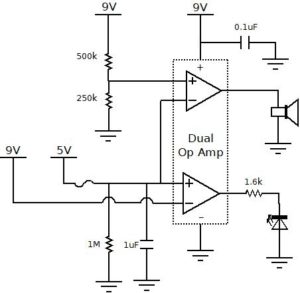
To actually detect when the power has gone out we are going to use an op-amp configured as a comparator. The battery voltage is connected to the op-amps positive supply terminal as well as the positive input terminal through a voltage divider. The 5V is then connected to the negative input terminal.
One optional thing we should note on the 5V - If in your application you are concerned with the voltage floating when power is removed, you can add a high value resistor between 5V and ground. This will ensure that when power is removed, there is still a path to ground for the 5V preventing it from floating.
The voltage divider in our case should be roughly 3:1 such that the 9V battery voltage gets divided down to roughly 3V at the input to the op-amp. This ensures that the negative terminal is always at a higher voltage than the positive terminal while your house has power.
Connecting your local ground to the negative supply terminal of the op-amp will keep its output voltage at ground potential while the 5V is present. When there is a power outage and the 5V disappears, the positive input terminal becomes greater than the negative supply terminal and the op-amp output drives to 9V (because that's what is connected to the positive supply terminal).
The 3:1 voltage divider will draw battery current at all times, so it is important to use large value resistors. I've used a 250k and 500k resistor for my divider which will draw 12uA.
Now we need to sound the buzzer. The buzzer has to be powered from 9V, and has to draw a low enough current as to be powered from an op-amp. For this task we'll use the CUI-1375-80T from CUI. With an operating voltage range of 3V to 16V and a current draw of 7mA, it fits nicely with what we need, plus it sounds off at 80dB.
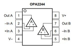
The op-amp we selected to run everything is the OP2244PA from Texas Instruments. It can output up to 25mA and will easily handle 9V. The other benefit is that it has 2 op amps within the same package, so we can use just the one part and implement the low battery circuit with it as well. But most importantly, it draws less than 0.1mA from the battery.

Dual Op Amp
To detect a low battery, we will use the second op amp circuit in the OP2244PA device. By connecting the positive input terminal to the 5V source, and the negative terminal to the 9V source, the output will drive high when the 9V battery voltage drops below 5V.
By connecting an LED to the output, with the appropriate current limiting resistor, we will then be lighting the LED up when the battery voltage drops below 5V. The LED we had lying around was the LTL2R3KRD-EM from Lite-On. It's forward voltage is 1.8V at 2mA, so when our battery drops to 5V and turns on this LED, we need a current limiting resistor of 1.6k ohms.
Now we'll just add a couple capacitors to help filter out any potential noise, and a fuse on the input (we used a 200mA resetable fuse) to protect against an accidental short in the circuit. And thats it, we've finished the power alarm!
Check out the circuit diagram below and stay tuned for our final post for this project where we will make a video of the circuit in operation!

Power Alarm Circuit Diagram
______
Help Support our work!

