Parts for the water alarm
Last time we sorted out the front end of circuit, so now lets pick the last of our parts.
To start, lets pick our battery. For this project, we're going to use a 9V battery. We are choosing 9V because it's easily connected with a snap on terminal and doesn't need a holder (you can adhere it with tape, a zip tie, etc).
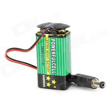
9V Battery with snap on terminal
Next lets choose the wireless interface (for the those who want to connect it to a wireless network). We don't want to break the bank, and we don't want to spend alot of time on implementing a solution from scratch. So we're going to pick an inexpensive wireless module. We've picked the ESP8266 based WRL-13678 from sparkfun. It has a through hole footprint, which makes it hand solderable and it utilizes simple AT commands to control the device.
Now we need a microcontroller to talk to the wireless module and because the WRL-13678 is a 3.3V part, we will need to select a micocontroller that is 3.3V compatible. I'm going to select an Atmel part (because my programmer is an ATMEL ICE). We need a part that can implement a UART to communicate with the module, and has enough IO to trigger the alarm, as well as monitor for water. We also want to be able to hand solder the part. Lets pick the low cost ATtiny 4313, which we can also breadboard.
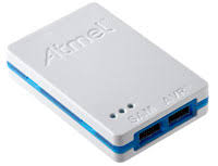
My Trusty Programmer
We want the alarm to be controlled by the micro controller. So we want to pick a part that can work below 3.3V with some margin, otherwise we will be designing a silent alarm. the AI-3035-TWT-3V-R from PUI audio, will work at the voltages we want, is easily hand solderable, is internally driven, and can sound off at 100dBA.
To power it all we will need a 3.3V source to power the electronics. We will need to step down the 9V battery to 3.3V. To save battery life we will use a switching regulator. The VXO7803-500 from CUI is hand solderable, can support the current needed for the wireless module as well as the rest of the circuit. It will also tolerate a fully charged 9V battery at its input and it is inexpensive.
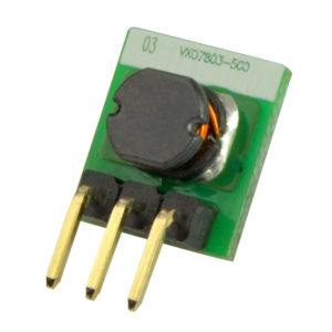
VXO78-500 Power Supply
Lastly we will use an op amp, configured as a comparatot to implement the low battery detector.
Check back soon!
______
Help Support our work!