Water Alarm Design
In our last post we outlined what we wanted the water alarm to do, so now its time to plan our design. Lets dive right in.
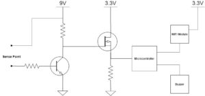
Block Diagram
Above you can see a simple block diagram of what we are building, and the most important part is the transistor. Its job is to turn on in the presence of water
- Transistor
The first question we have to answer was whether to use a MOSFET or a BJT. In this instance I chose to use a BJT. The gate of a mosfet would need approximately 10% of our battery voltage to turn on and because of the large variablity of the resistance of the water (it ranges from a few hundred ohms for salt water to as much as 1M ohm for distilled water) I had less faith in accurately and consistently enabling the gate of the MOSFET. The BJT on the other hand is current controlled and will conduct (albeit to varying degrees) with a wide range of drive currents.
We want a BJT that can handle the 9V battery across Vce, and we want to be able to turn it on with a reasonably low Vbe and base current. The BC546/547 fits the bill nicely.
We need the Base to "turn" on the BJT and allow current to flow through the collector-emitter of the transistor.
The maximum collector current is 100mA, so we will design our nominal case for 10mA.
The base current required is given by:
Ib = Ic/B
After plugging in the worst case B of 110 for our transistor, we see that we require a minimum of 91uA of base current to saturate this BJT and get 10mA flowing through the collector. We will therefore design to 0.5mA to accommodate the variablity of the resistance measurement of water across the sensor.
To achieve that we need to select an appropriate resistor between the sensor and the base of the transistor.
Rbtotal = (Vsensor - Vbe)/Ib
From examining the datasheet of your battery you can determine the lowest voltage to operate your battery at. Select a point on the curve just before the voltage decay accelerates. For this battery, the plot below shows it as 7.5V. As the sensor is connected to the battery voltage, we will set this to Vsensor.
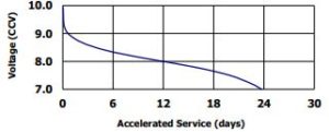
9V Energizer 522 battery discharge curve
After plugging in a Vbe of 0.7V, and Ib of 0.5mA, we derive an Rb of 13.6k ohms.
Lets assume that the water our sensor measures presents a 1.5k ohm resistance, then we would require a base resistor of:
Rb = 13.6k - 1.5k = 12.2k
which conveniently is a standard 1% value.
In the event of a short at the BJT input we don't want to blow up the FET, so we want to put a current limiting resistor at the collector. The value of that resistor can be derived from the following:
Rc = (Vbat - Vce)/Ic
plugging in 9V for Vbat, 0.25V for Vce and 10mA for Ic, we get
Rc = 875 ohms (910 ohms selected because its a standard value)
PFET
Because the BJT is running on 9V, we need a way to convert the output of the BJT sense circuit to digital logic levels. For that we are going to use a PFET.
For anyone who wants to stop here and not bother with the microcontroller and wireless module, we can use the PFET to turn on the buzzer directly and be done.
A PFET will conduct when the voltage at its source pin is greater that the voltage at its gate pin. Because our BJT only turns on in the presence of water, the gate pin of the PFET will be at 9V until water is detected. Once the BJT detects water, it turns on and shorts the PFET gate pin to 0V. When this happens the PFET will conduct allowing current to flow to the buzzer, sounding the alarm.
The PFET we are going to select will need to work with 9V connected at its source and its gate, so we will pick a part thats rated for a minimum of 12V. We also want a through hole part, so we can breadboard it (or easily hand solder). We will see in our next post that the buzzer works with as little as 10mA, and so we will selected a part that is rated for at least 100mA. Lastly as will be shown in the next post, the digital logic for the microcontroller is 3.3V, so we'll need a part that will operate with a minimum Vgs threshold of -3.3V.
Given the above criteria, the ZVP4424A from Diodes Inc has been selected.
Now, before we move on to creating the digital logic, lets close off the case for those who want to just connect the buzzer now and close the browser.
When the BJT enables the PFET we want to limit the current to around 10mA, which would require a resistor in the neighborhood of 900 ohms... so we'll just use another 910 ohm resistor. Connect the resistor between the drain pin of the PFET and the + pin of the buzzer. Connect the other end of the buzzer to ground and the source pin of the PFET to 9V, and you are good to go. And now back to the original plan...
To create the digital logic signal, we will connect 3.3V to the PFET source pin, and connect a resistor to ground at the drain pin. We'll select the resistor such that it limits the current to a couple of mA. To shorten our shopping list we'll use the 910 ohm value from earlier, which will limit the current to roughly 3.5mA.
We then also connect the GPIO pin from the microcontroller to the drain pin. The result is that when water is sensed by the BJT, the PFET shorts 3.3V to the GPIO pin. When nothing is detected, no current flows through the PFET, and the GPIO pin remains low... Voila, we've given our analog input a digital output.
In our next post we will outline the design of the rest (digital portion) of the circuit.
Check back soon!
______
Help Support our work!
